
Documentation
ATTENTION: The documentation below is outdated and will be replaced soon.
1 Brief introduction
2 Getting started
3 alien model
3.1 Physics framework
3.1.1 Rigid body motion
3.1.2 Thermodynamics
3.1.3 Space
3.1.4 Entities
3.1.4.1 Cell
3.1.4.2 Cell cluster
3.1.4.3 Energy particle
3.1.4.4 Token
3.2 Information processing model
3.2.1 Processing scheme
3.2.2 Cell function programming
3.2.2.1 Computer
3.2.2.2 Propulsion
3.2.2.3 Scanner
3.2.2.4 Weapon
3.2.2.5 Constructor
3.2.2.6 Sensor
3.2.2.7 Communicator
3.3 Energy guidance system
3.4 Simulation parameters
1 Brief introduction
ALiEn is a shortform for artificial life environment and denotes an artificial life simulation program aiming to compute digital organisms in artificial ecosystems and (pre-)biotic evolution processes. The main feature is that it combines a realistic physical framework including kinematic and thermodynamic processes with a computational model that allows to describe the behavior and purposeful interventions of the simulated bodies. The bodies have an inner structure which are modeled by planary graphs where the nodes corresponds to elementary cells and the edges to communication channels (connections). In the following we briefly explain the underlying computational as well as the physical model.
Information processing model: Cell clusters implement their behavior algorithms in the cells and their connections. The topology of the cluster allows to implement loops, branches, distributed algorithm etc. Computations as well as input and output operations of the clusters are performed on the cells via tokens. Every token contains a memory and provokes execution of cell functions. Various cell functions such as computations, sensoring, constructing, attacking external cells etc. are available. After a cell has executed its function the token spreads to adjacent cells by a specific rule. This will be decided on the basis of the branch number attributed to every token and cell. The rule is that the token spreads to an adjacent cell if the branch number of the cell is one larger than the token branch number modulo a fixed constant.
Physical model: Every cell cluster is embedded in a physical 2D space and performs rigid body movements taking linear and angular momentums into account. If two clusters collide they may merge provided the velocities are high enough and the touching cells on both clusters are able to establish bonds. Otherwise a collision takes place. Single cells of a cluster might be destroyed after a collision if the forces exceeds a certain threshold. Furthermore cells as well as tokens have an internal energy value and emit energy particles from time to time. Radiation lowers their internal energy and may finally lead to disintegration. But if on the contrary energy particles collide they may form a new cell if their energy values together are high enough.
2 Getting started
In this section you will get to know the alien simulator. A detailed reference is given in Section 4 whereas in Section 3 you find information about the model it is based on.
At first you should start a new simulation by clicking Simulation -> New in the menu. Some initial energy can be placed in the simulation. It is represented as particles that move in an empty space. For a universe of size 1200 x 600 one can choose, e.g., a value of 1e+7. The simulation parameters and symbol map have meaningful default values and can be keept as they are for the moment. Clicking OK generates a new universe which particles carrying the initial energy.
There are two modes for viewing the simulation: pixel view and item view. The pixel view is set as default and gives a overview about where the particles and cells are situated. Cells can have different colors. The default color is blue. The particles are shown in red. The item view however gives a much more detailed insign. One can not only inspect precise position, velocity, energy and internal states but also change them. To switch between these modes View -> Editor has to be toggled in the menu. It is recommended to zoom into the universe before switching to the item view. In that view one can select one or more particles or cells. If one selects just one entity by clicked on it all the internal informations on additional windows in the upper left corner are shown.
It is also possible to load some collection of cells and particles into the simulation. Some standard examples are provided with this software. One can load them in Collection -> Load into the current universe. For instance one may load a replicator collection. It is recommended to use the item view for loading collections. If one would like to load the collection more then one time at different positions please click on Collection -> Random multiplier to clone the collections as many times as desired.
To start the simulation please toggle Simulation -> Run. On the bottom status line one should see the current timestep and the timesteps per second (TPS). Also limiting TPS is possible there by clicking on the restrict TPS-button. Beside that button one can enter a TPS limit. Toggling again Simulation -> Run will pause the simulation. Loading and saving is also possible via the Simulation menu entries. Sometimes it is convenient to restore a universe via snapshots. In Simulation -> Snapshot and Simulation -> Restore one can save the universe in temporary memory and restore it at any time later.
3 alien model
The alien model combines a physical and a computation model and can be seen some realization of artificial programmable matter.
Throughout this section simulation parameters (such as mutation probability) are denoted by the bracket notation [...] -> ... -> [...]. A overview of the parameters is given in 4.4.2 Simulation parameters.
3.1 Physics framework
3.1.1 Rigid body motion
A motion of the cell clusters is calculated via rigid body dynamics. Thus every cluster performs a linear movement and a rotation with respect to its center position. Collision of two clusters result in one of the following scenario: cluster fusion or collision. The former case takes place if the relative velocities of the touching cells exceeds the fusion velocity and if each cell is able to establish new bonds. In the fusion process kinetic energy is transformed into internal energy whereas the linear and angular momentum is preserved. In the latter case a rigid collision is conducted, which preserves the overall kinetic energy (rotation and linear part) of the involving objects.
3.1.2 Thermodynamics
Each cell object looses internal energy through radiation. This process is realized by emitting energy particles to its environment. These particles have a velocity but no mass and they carry a specific amount of energy. Whenever the internal energy of a cell is below some value (see [cell properties]->[min value]) it becomes unstable and transforms itself into an energy particle. It may also lead to a destruction of the superordinate cell cluster into two or more separated parts. If two energy particles collide they form a single particle with the combined energy. When the amount of energy exceeds a given value needed to form a cell (see [cell properties]->[min value]) and its kinetic energy, the particle transforms with a fixed probability (see [cell properties]->[transformation probability]) into a cell. Therefore dynamic creation and destruction processes of cells are implemented.
3.1.3 Space
Every cell cluster and energy particle object is embedded in a common space where all the physical actions take place. Topologically the space is 2D torus, which means that the opposite boundaries are to be considered as the same.
3.1.4 Entities
3.1.4.1 Cell
The cells are the main entities in alien. They have a position in space, an internal energy value, they can establish bonds with other cells, and, moreover, they have an associated cell function and may store tokens. Cells are able to form bonds with other cells (see [cell properties]->[max bonds]). Cell clusters are simply set of cells connected together. Physically they rotate and move with respect to their center position. This type of entity carries energy through space. It moves with a particular velocity but has no mass. Energy particle can fuse if they collide together and be absorbed if they collisde with cells. Furthermore every cell emits energy particle from time to time and thus looses internal energy. Token are used to coordinate the information processing capability of the cells. They carry a memory storage and have an internal energy. 3.1.4.2 Cell cluster
3.1.4.3 Energy particle
3.1.4.4 Token
3.2 Information processing model
3.2.1 Processing scheme
The cells feature information processing capabilities. As soon as a token passes a cell the specific cell function is invoked (see next section for more details). During this process memory of the cell as well as of the token might be changed. Also certain physical operations might be performed. After the cell function has finished its processing the token invokes its energy guidance system, increments its so-called branch number and spreads to adjacent cells that possess the same branch number. Hence cells and tokens have associated branch numbers that might change during processing. The branch number is incremented by using a modulo arithmetic, see [cell properties]->[max token branch number]. If there are more than one cells to be considered the token is duplicated and the required energy is consumed from the cells. By making use of duplicating tokens parallel algorithms can be implemented. If there is no cell on which the token can pass the token will be destroyed and its internal energy is transferred to the current cell. The computer cell function provides a little executable program consisting of instructions in machine code. The machine code is stored in the cell. Their instructions can access the memory storage of the cell as well as of the token. Both memory storages can have a maximum size of 256 bytes and all variables and addresses are one byte long. In calculations all values are interpreted as 8 bit signed integers. The number of instructions a computer cell function can have is indicated in [cell properties]->[computer]->[max instructions], the size of the cell memory in [cell properties]->[computer]->[cell memory size] and the size of the token memory in [cell properties]->[computer]->[token memory size].
The token branching is illustrated in the picture below. It shows token spreading on certain cells which are part of a cluster. The branch numbers are revealed for the cells and the tokens (red circles) before invoking the cell function. In this example the tokens possess the same branch number as the underlying cell. However the cell function may change this number if desired (this is not the case in the example). In this way the token branching can be controlled. 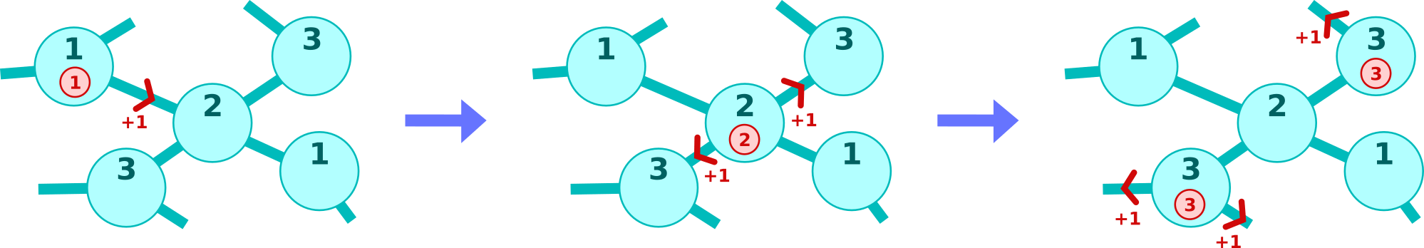
3.2.2 Cell function programming
3.2.2.1 Computer
Each instruction consists of three bytes (3x8=24 bits) with the following assigment:
| abbreviation | description | bits |
|---|---|---|
| opCode | determines the type of operation | 20-23 |
| opType1 | how the value of operand1 are interpreted, e.g. constant, address to memory, etc. (see below) | 18-19 |
| opType2 | how the value of operand2 are interpreted | 16-17 |
| opValue1 | value of operand1 | 8-15 |
| opValue2 | value of operand2 | 0-7 |
and the following values for opCode
| value of opCode | syntax | description |
|---|---|---|
| 0 | mov | copy operand: op1 := op2 |
| 1 | add | add operands: op1 := op1 + op2 |
| 2 | sub | subtract operands: op1 := op1 - op2 |
| 3 | mul | multiply operands: op1 := op1 * op2 |
| 4 | div | divide operands: op1 := op1 / op2 |
| 5 | xor | bitwise XOR of operands: op1 := op1 XOR op2 |
| 6 | or | bitwise OR of operands: op1 := op1 OR op2 |
| 7 | and | bitwise AND of operands: op1 := op1 AND op2 |
| 8 | if op1 > op2 | compare if operand1 is greater than operand2 |
| 9 | if op1 >= op2 | compare if operand1 is greater or equal than operand2 |
| 10 | if op1 = op2 | compare if operand1 is equal to operand2 |
| 11 | if op1 != op2 | compare if operand1 is not equal to operand2 |
| 12 | if op1 <= op2 | compare if operand1 is less or equal than operand2 |
| 13 | if op1 < op2 | compare if operand1 is less than operand2 |
| 14 | else | invoke else-clause in comparison |
| 15 | endif | finish comparison |
opValue1 and opValue2 refer to 8 bit values with a variable meaning determined by opType1 and opType2, respectively. Note that there are no instructions for loops. They can be realized with circular constructions of cell connections.
| value of opType1 | syntax | description |
|---|---|---|
| 0 or 3 | [opValue1] | operand1 points to a byte in token memory |
| 1 | [[opValue1]] | operand1 points to a pointer to a byte in token memory |
| 2 | (opValue1) | operand1 points to a byte in cell memory |
Examples
Let us give some examples fo instructions in assembler notation (hexadecimal values are preceded by 0x).
| syntax | description | opCode | opType1 | opType2 | opValue1 | opValue2 | hex code |
|---|---|---|---|---|---|---|---|
| mov (128), 10 | copies the value 10 to cell memory at address 128 | 0 | 2 | 3 | 128 | 10 | 0x0B800A |
| mul (32), [[64]] | multiplies the value from cell memory at address 32 with the value from token memory at the address that is found in token memory at address 64 | 3 | 2 | 1 | 32 | 64 | 0x392040 |
A simple cell program consisting of 5 instructions may look like as follows:
if [10] = (0)
mov [10], 0
else
add [10], 1
endif
On the first line it is checked if the content of token memory at address 10 equals the content of cell memory at address 0. If this is true the content of token memory at address 10 is set to 0 otherwise it is incremented by 1. A computer cell function stores n instructions where n is specified by [cell function properties]->[computer]->[max instructions].
3.2.2.2 Propulsion
A controlled acceleration can be performed by the propulsion cell function. It uses three input bytes and produces one output byte. Both are read and stored in the token memory. Their addresses depend on the implementation. In the following we introduce symbolic names for them.
| syntax | access type | description |
|---|---|---|
| PROP_OUT | output | returns the state of the after the process (see below) |
| PROP_IN | input | contains the command (see below) |
| PROP_IN_ANGLE | input | contains CODED_ANGLE(alpha) where alpha is the angle in which the acceleration takes place |
| PROP_IN_POWER | input | determines the intensity of the acceleration |
The direction of acceleration is determined by the command PROP_IN and possibly by PROP_IN_ANGLE. All angles are always measured clockwise with respect to the axis given by the invoked cell and the cell where the token came from (see picture below). 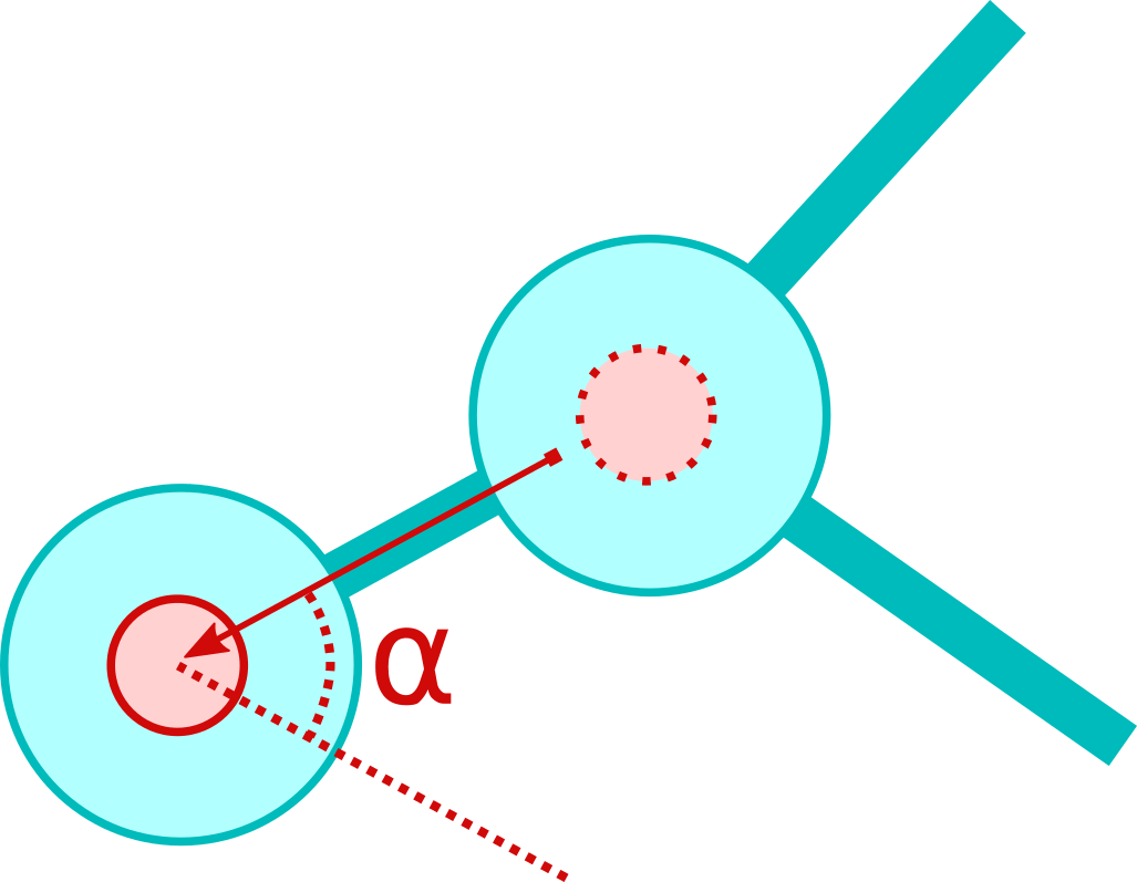
The function CODED_ANGLE above transforms an angle from degree into an 8 bit representations. More precisely, angles from 0 to 179 degree are mapped to 0 until 128 (dec) and the angles from -180 to 0 degree are mapped to 128 until 256 (= 0 mod 256).
PROP_IN may take the following values.
| value of PROP_IN (modulo 7) | syntax | description |
|---|---|---|
| 0 | PROP_IN::NOTHING | do nothing |
| 1 | PROP_IN::BY_ANGLE | contains the command (see below) |
| 2 | PROP_IN::FROM_CENTER | contains CODED_ANGLE(alpha) where alpha is the angle in which the acceleration takes place |
| 3 | PROP_IN::TOWARD_CENTER | determines the intensity of the acceleration |
| 4 | PROP_IN::ROTATION_CLOCKWISE | accelerate in a direction that increases clockwise rotation |
| 5 | PROP_IN::ROTATION_COUNTERCLOCKWISE | accelerate in a direction that increases counterclockwise rotation |
| 6 | PROP_IN::DAMP_ROTATION | accelerate in a direction that decreases current rotation |
The output given in PROP_OUT can attain the values given below.
| value of PROP_OUT | syntax | description |
|---|---|---|
| 0 | PROP_OUT::SUCCESS | acceleration performed |
| 1 | PROP_OUT::SUCCESS_DAMPING_FINISHED | rotation of the cluster is approximately 0, no further damping possible |
| 2 | PROP_OUT::ERROR_NO_ENERGY | not enough energy available for acceleration |
3.2.2.3 Scanner
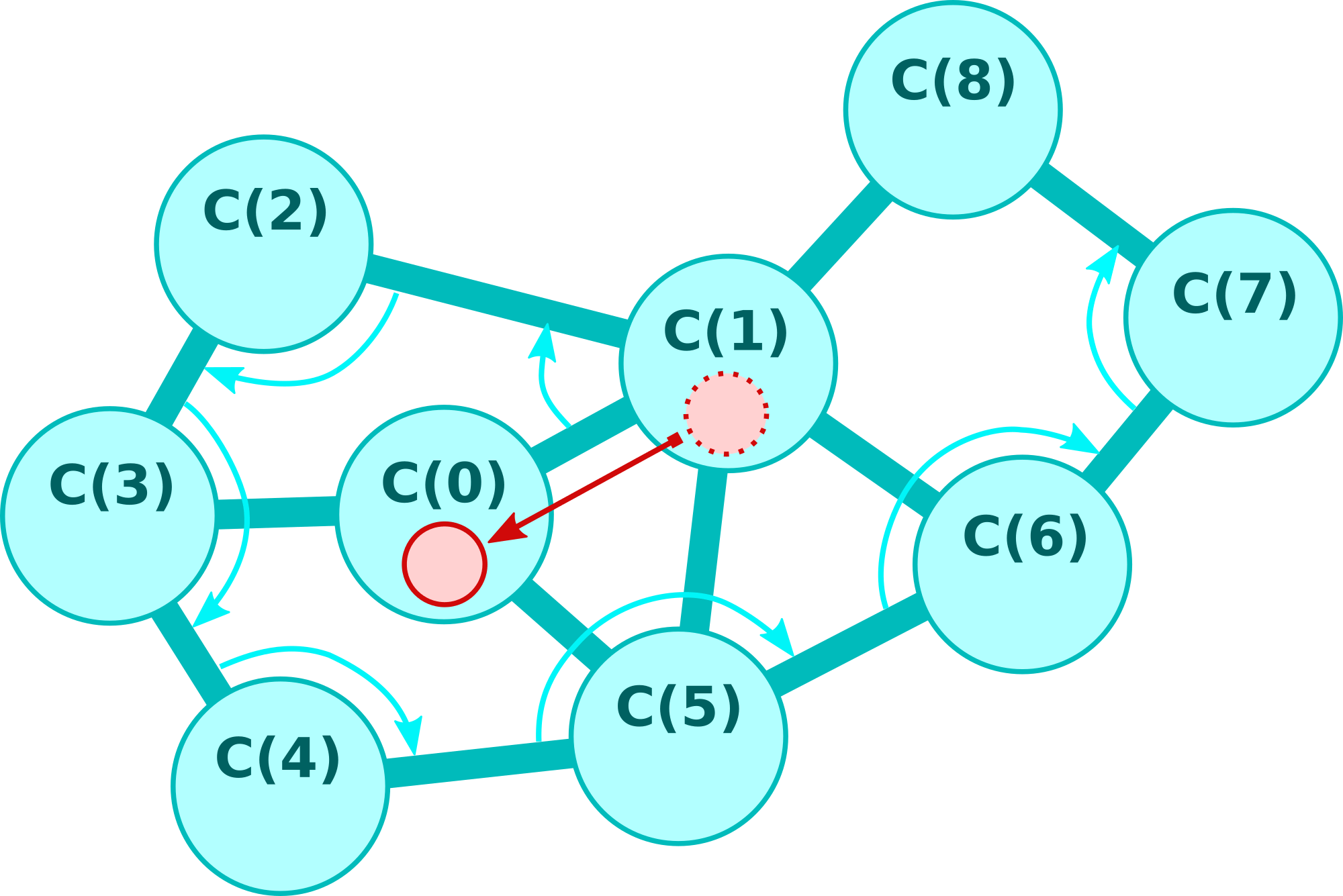
The task of the scanner cell function is to determine the cells of its own cluster. It provides the relative position and the precise internal data of the cells in an iterative procedure. The iteration depth is controlled by an index. The algorithm works as follows (the cell on which the scanner points to at index i is denoted by C(i)).
| • index = 0: | scanner points to the cell itself, which is C(0) |
| • index = 1: | scanner points to the cell C(1) where the token which invokes the scan comes from |
| • index = 2: | scanner points to the cell C(2) which is connected to C(1) and next to C(0) in a clockwise sense |
| ... | |
| • index = i: | scanner points to the cell C(i) which is connected to C(i-1) and next to C(i-2) in a clockwise sense and different from C(0) to C(i-3) |
The scanner cell function uses the subsequent bytes for communication.
| syntax | access type | description |
|---|---|---|
| SCANNER_OUT | output | returns the state after the process (see below) |
| SCANNER_INOUT_CELL_NUMBER | input and output | index i of the cell C(i), value will be incremented after scanning or set to 1 if a restart takes place |
| SCANNER_OUT_MASS | output | returns the mass (number of cells) of the cluster |
| SCANNER_OUT_ENERGY | output | returns the energy value of the cell C(i) |
| SCANNER_OUT_ANGLE | output | returns CODED_ANGLE(180-alpha) where alpha is the angle (in degree) between the vectors C(i)-C(i-1) and C(i-2)-C(i-1) (see above for a definition of CODED_ANGLE) |
| SCANNER_OUT_DISTANCE | output | returns CODED_LEN(len) where len is the distance between C(i-1) and C(i) |
| SCANNER_OUT_CELL_MAX_CONNECTIONS | output | returns the maximal number of possible connections of cell C(i) |
| SCANNER_OUT_CELL_BRANCH_NO | output | returns the branch number of cell C(i) |
| SCANNER_OUT_CELL_FUNCTION | output | returns the cell function of cell C(i) (see below) |
| SCANNER_OUT_CELL_FUNCTION_DATA | output | returns the internal data for the cell function of cell C(i) (if the cell has a computer cell function it contains the coded instructions) |
The reason why SCANNER_OUT_ANGLE returns CODED_ANGLE(180-alpha) and not simply CODED_ANGLE(alpha) is to be compatible with the constructor cell function (see below).
The function CODED_LEN converts a spatial length unit into an 8 bit representation. The length 0.0 is mapped to 0 and 1.0 is mapped to 100 (dec). Results above 255 are coded as 255.
The state of the scanner cell function after processing is stored in SCANNER_OUT, which can attain the following values.
| value of SCANNER_OUT | syntax | description |
|---|---|---|
| 0 | SCANNER_OUT::SUCCESS | scanning has been performed |
| 1 | SCANNER_OUT::FINISHED | scanning has been performed at last reachable cell |
| 2 | SCANNER_OUT::RESTART | scanning has been restarted and performed at C(0) and SCANNER_INOUT_CELL_NUMBER has been set to 1; this happens when i is higher than the number of reachable cells |
The cell function of the scanned cell is stored in SCANNER_OUT_CELL_TYPE and attains the following values.
| values of SCANNER_OUT_CELL_FUNCTION | syntax | description |
|---|---|---|
| 0 | SCANNER_OUT_CELL_FUNCTION::COMPUTER | scanned cell has a computer cell function |
| 1 | SCANNER_OUT_CELL_FUNCTION::PROP | scanned cell has a propulsion cell function |
| 2 | SCANNER_OUT_CELL_FUNCTION::SCANNER | scanned cell has a scanner cell function |
| 3 | SCANNER_OUT_CELL_FUNCTION::WEAPON | scanned cell has a weapon cell function |
| 4 | SCANNER_OUT_CELL_FUNCTION::CONSTR | scanned cell has a construction cell function |
| 5 | SCANNER_OUT_CELL_FUNCTION::SENSOR | scanned cell has a sensor cell function |
3.2.2.4 Weapon
If invoked, the weapon cell function looks for neighboring cells that are not part of the cluster and in the direct vicinity. If such cells are present, a part of their energy amount indicated in [cell properties]->[weaon]->[strength] will be stolen. One half of the stolen energy amount is tranferred to the invoking token while the half to the cell itself. There is no input only one output byte, which is named as WEAPON_OUT and takes the following values.
| value of WEAPON_OUT | syntax | description |
|---|---|---|
| 0 | WEAPON_OUT::NO_TARGET | no neighboring cells have been found |
| 1 | WEAPON_OUT::STRIKE_SUCCESSFUL | neighboring cells have been found and attacked |
3.2.2.5 Constructor
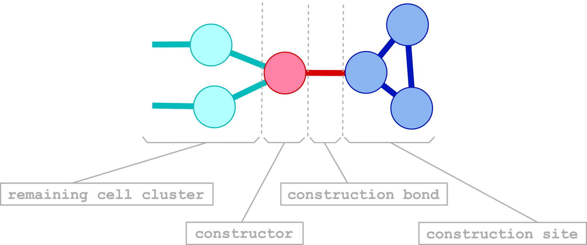
The aim of the 'constructor cell function' (the corresponding cell will be denoted as `constructor') is not only to create a new cell but also to bond and create new cell structures. To this end, a part of the surrounding of the cell is be taken as a construction site. When the constructor creates a new cell the whole construction site will be moved and rotated if necessary (the remaining part as well) in order to obtain free space for the new cell. This may take several processing steps. When this is completed the new desired cell is placed and bonded to the construction site. The constructor can be seen as an artificial equivalent to a biological ribosome, which creates and folds proteins from amino acides.
A typical situation is illustrated in the subsequent picture.
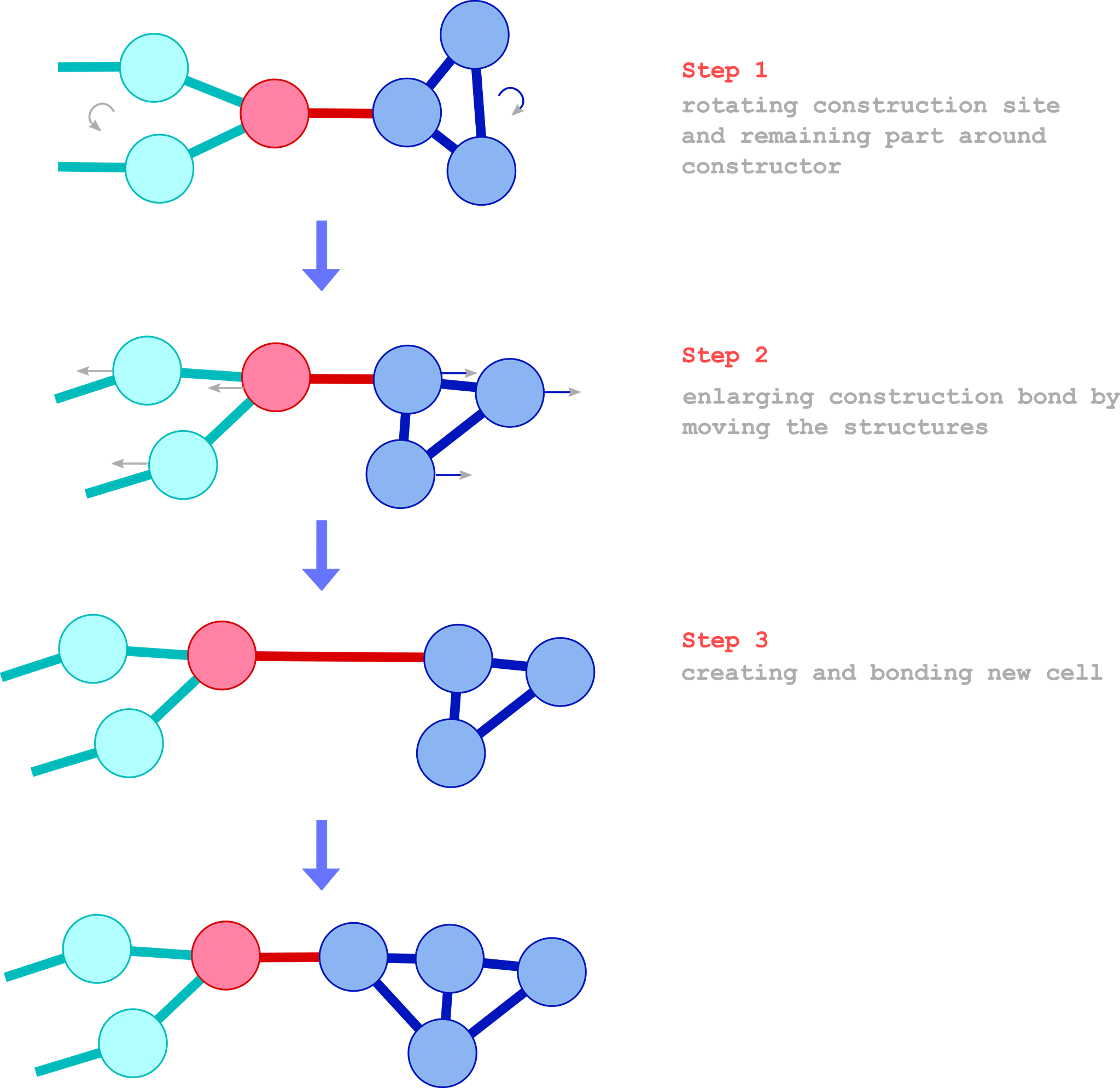
In the next picture a typical construction process is shown.
After this introductory example we are going to explain the programming of the constructor. For convenience, most arguments coincide with output bytes of the scanner and thus share the same addresses in the token memory. This allows us to use certain output bytes of the scanner directly as input bytes for the constructor in order to easily replicate the cluster's own structure. The constructor uses the following bytes.
| syntax | access type | description |
|---|---|---|
| CONSTR_OUT | output | returns the state after the process (see below) |
| CONSTR_IN | input | contains the command (see below) |
| CONSTR_IN_OPTION | input | additional parameters for construction (see below) |
| CONSTR_INOUT_ANGLE | input and output | contains CODED_ANGLE(alpha) where alpha is the angle of which the construction site should still be rotated (see above for a definition of CODED_ANGLE) note: address coincides with SCANNER_OUT_ANGLE |
| CONSTR_IN_DIST | input | CODED_LEN(len) where len is the distance of which the the construction site should be moved (see CODED_LEN from scanner cell function) note: address coincides with SCANNER_OUT_DISTANCE |
| CONSTR_IN_CELL_MAX_CONNECTIONS | input | contains the maximal number of possible connections for the new cell; if 0 then the maximal number of connections will be automatically determined such that no further connections will be possible (recommended as standard setting) note: address coincides with SCANNER_OUT_CELL_MAX_CONNECTIONS |
| CONSTR_IN_CELL_BRANCH_NO | input | contains the branch number for the new cell note: address coincides with SCANNER_OUT_CELL_BRANCH_NO |
| CONSTR_IN_CELL_FUNCTION | input | contains the cell function for the new cell (same values as SCANNER_OUT_CELL FUNCTION) note: address coincides with SCANNER_OUT_CELL_FUNCTION |
| CONSTR_IN_CELL_FUNCTION_DATA | input | contains the internal data for the cell function for the new cell note: address coincides with SCANNER_OUT_CELL_FUNCTION_DATA |
The output byte CONSTR_OUT has one of the following values.
| value of CONSTR_OUT | syntax | description |
|---|---|---|
| 0 | CONSTR_OUT::SUCCESS | construction of a new cell was successful |
| 1 | CONSTR_OUT::SUCCESS_ROT | Operation was successful although a new cell has not been constructed because the construction site needs to be rotated first. A part of the rotation has been achieved and CONSTR_INOUT_ANGLE has been updated. To continue the construction process, the constructor should be invoked again with the current token. |
| 2 | CONSTR_OUT::ERROR_NO_ENERGY | not enough energy to perform the construction |
| 3 | CONSTR_OUT::ERROR_OBSTACLE | construction could not be performed because of overlapping cells (i.e. obstacle(s)) |
| 4 | CONSTR_OUT::ERROR_CONNECTION | construction site is connected to the remaing cluster besides the constructor |
| 5 | CONSTR_OUT::ERROR_DIST | CONSTR_IN_DIST is too large (which means that their value converted to spatial units exceeds [cell properties]->[max distance]) |
The following commands are possible.
| values of CONSTR_IN (modulo 4) | syntax | description |
|---|---|---|
| 0 | CONSTR_IN::NOTHING | do nothing |
| 1 | CONSTR_IN::SAFE | move construction site and construct new cell only if there are no overlapping cells including the cluster's own cells |
| 2 | CONSTR_IN::UNSAFE | move construction site and construct new cell only if there are no overlapping cells with other clusters |
| 3 | CONSTR_IN::BRUTEFORCE | rotate and move construction site and construct new cell regardless of overlapping cells (which may lead to destruction) |
Moreover, the following options are possible.
| values of CONSTR_IN_OPTION (modulo 7) | syntax | description |
|---|---|---|
| 0 | CONSTR_IN_OPTION::STANDARD | standard construction process |
| 1 | CONSTR_IN_OPTION::CREATE_EMPTY_TOKEN | perform cell construction process and create an empty token on the new cell |
| 2 | CONSTR_IN_OPTION::CREATE_DUP_TOKEN | perform cell construction process and create a copy of the current token on the new cell |
| 3 | CONSTR_IN_OPTION::FINISH_NO_SEP | perform cell construction process and finalize the construction size but let them connected to the constructor |
| 4 | CONSTR_IN_OPTION::FINISH_WITH_SEP | perform cell construction process, finalize the construction size and disconnect it from the constructor |
| 5 | CONSTR_IN_OPTION::FINISH_WITH_SEP_RED | perform cell construction process, finalize the construction size and disconnect it from the constructor, reduce number of maximal connections of the cell that becomes disconnected from the constructor by 1 |
| 6 | CONSTR_IN_OPTION::FINISH_TOKEN_WITH_SEP_RED | perform cell construction process, finalize the construction size and disconnect it from the constructor, reduce number of maximal connections of the cell that becomes disconnected from the constructor by 1, create empty token |
The construction procedure works in the following way (compare with the illustration above): When the token first invokes the constructor it will rotate the construction site and the remaining part (contrariwise) around the constructor in order to reach the specified angle in CONSTR_INOUT_ANGLE. When the whole cell cluster or the angle is large this process may take several steps and, in this case, the constructor performs only a partial rotation and returns the remaining angle in CONSTR_INOUT_ANGLE. After invoking the constructor with the resulting token again and again it will finish the rotation. Then the construction site will be shifted with a distance specified in CONSTR_IN_DIST and a new cell will be created and connected to the constructor. The new cell will also bond to neighboring cells in the construction site (the maximal number of connections are speficied in CONSTR_IN_CELL_MAX_CONNECTIONS). We remark that the token on the constructor cannot pass to the construction site because the token passage is blocked in this situation. For the completion of the construction process (see CONSTR_IN_OPTION) the construction site will be disconnected from the constructor.
3.2.2.6 Sensor
The task of the sensor cell function is to detect other cell clusters in the vicinity. There are essentially two different modes. In the first mode (called mode I in the following) the sensor scans a particular direction up to a certain distance (specified by [cell function properties]->[sensor]->[range]) and, if successful, returns the distance of the closest other cell cluster. In the second mode (mode II) the sensor scans its whole vicinity to detect a cell cluster. If successful it returns the angle and the distance of that cluster. In both modes a minimum and a maximum mass for detection can be specified in advance. The mass corresponds to the number of cells of a cluster. The sensor uses the following bytes.
| syntax | access type | description |
|---|---|---|
| SENSOR_OUT | output | returns the state after the process (see below) |
| SENSOR_IN | input | contains the command (see below) |
| SENSOR_INOUT_ANGLE | input and output | CODED_ANGLE(alpha) where in mode I alpha specifies the angle for scanning (input byte); in mode II alpha contains the angle in which a cell cluster has been found (output byte) (see above for a definition of CODED_ANGLE) |
| SENSOR_IN_MIN_MASS | input | minimum mass of the cell clusters to detect |
| SENSOR_IN_MAX_MASS | input | maximum mass of the cell clusters to detect |
| SENSOR_OUT_MASS | output | mass of the detected cell cluster; it has the values 127 if the mass is above 127 |
| SENSOR_OUT_DISTANCE | output | distance of the detected cell cluster; it has the values 127 if the distance is above 127 |
The output byte SENSOR_OUT has one of the following values.
| values of SENSOR_OUT | syntax | description |
|---|---|---|
| 0 | SENSOR_OUT::NOTHING_FOUND | sensor has nothing found |
| 1 | SENSOR_OUT::CLUSTER_FOUND | sensor has detected an other cell cluster; its mass is stored in SENSOR::OUT_MASS, its distance in SENSOR::OUT_DISTANCE and its angle in SENSOR::INOUT_ANGLE |
A sensor can process the following commands.
| values of SENSOR_IN (modulo 5) | syntax | description |
|---|---|---|
| 0 | SENSOR_IN::DO_NOTHING | do nothing |
| 1 | SENSOR_IN::SEARCH_VICINITY | It invokes a wide-area scan for other cell clusters in all directions of the vicinity with radius specified in [cell function properties]->[sensor]->[range]. If a cell cluster is found with mass between SENSOR_IN_MIN_MASS and SENSOR_IN_MAX_MASS (then SENSOR_OUT is set to SENSOR_OUT::CLUSTER_FOUND) its angle is returned in SENSOR_INOUT_ANGLE, its distance in SENSOR_OUT_DISTANCE and its mass in SENSOR_OUT_MASS. Note that it is not guaranteed that all clusters can be detected in this way since the sensor uses a certain raster. The raster length is given by sqrt(SENSOR_IN_MIN_MASS)+3. |
| 2 | SENSOR_IN::SEARCH_BY_ANGLE | invokes a scan for other cell clusters in a particular direction specified by the angle in SENSOR_INOUT_ANGLE; output behavior is similar to SENSOR_IN::SEARCH_VICINITY |
| 3 | SENSOR_IN::SEARCH_FROM_CENTER | invokes a scan for other cell clusters in the direction given by the vector posCell - posMassCenter where posMassCenter denotes position of the mass center of the current cell cluster and posCell the position of the invoked cell; output behavior is similar to SENSOR_IN::SEARCH_VICINITY |
| 4 | SENSOR_IN::SEARCH_TOWARD_CENTER | invokes a scan for other cell clusters in the direction given by the vector posMassCenter - posCell (cf. above); output behavior is similar to SENSOR_IN::SEARCH_VICINITY |
3.2.2.7 Communicator
The communicator cell function allows to transmit and receive messages form other communicator cells in the vicinity. The message can be sent in one of the 256 channels. Furthermore relative position information given in angle and distance can be transmitted. As always, all angles are measured clockwise with respect to the axis given by the invoked cell and the cell where the token came from. The receivers obtains the transformed position (in angle and distance) with respect to their position and orientation. The following bytes are used to program the communicator.
| syntax | access type | description |
|---|---|---|
| COMMUNICATOR_IN | input | contains the command (see below) |
| COMMUNICATOR_IN_ANGLE | input | relative angle of a transmitted position |
| COMMUNICATOR_IN_DISTANCE | input | relative distance of a transmitted position |
| COMMUNICATOR_IN_CHANNEL | input | relative distance of a transmitted position |
| COMMUNICATOR_IN_MESSAGE | input | message |
| COMMUNICATOR_OUT_RECEIVED_ANGLE | output | relative angle of a position information belonging to a received message |
| COMMUNICATOR_OUT_RECEIVED_DISTANCE | output | relative distance of a position information belonging to a received message |
| COMMUNICATOR_OUT_RECEIVED_MESSAGE | output | received message |
| COMMUNICATOR_OUT_RECEIVED_NEW_MESSAGE | output | indicates if a message has been received since last retrieve (see below) |
| COMMUNICATOR_OUT_SENT_NUM_MESSAGE | output | number of communicator cells who have received the transmitted message |
The following commands can be processed.
| values of COMMUNICATOR_IN (modulo 4) | syntax | description |
|---|---|---|
| 0 | COMMUNICATOR_IN::DO_NOTHING | do nothing |
| 1 | COMMUNICATOR_IN::SET_LISTENING_CHANNEL | Sets the channel where the communicator can listen for messages sent by other communicator cells. The channel itself is set in COMMUNICATOR_IN_CHANNEL (see above). |
| 2 | COMMUNICATOR_IN::SEND_MESSAGE | Sends a message given by COMMUNICATOR_IN_MESSAGE to the channel COMMUNICATOR_IN_CHANNEL to nearby communicator cells. Nearby means in radius specified by the simulation parameter [cell function properties]->[communicator]->[range]. Furthermore a relative position information can be transmitted in COMMUNICATOR_IN_ANGLE and COMMUNICATOR_IN_DISTANCE as explained above. The output COMMUNICATOR_OUT_SENT_NUM_MESSAGE returns the number of communicator cells who received the message. |
| 3 | COMMUNICATOR_IN::RECEIVE_MESSAGE | If a message has been received since the last invoke COMMUNICATOR_OUT_RECEIVED_NEW_MESSAGE is set to COMMUNICATOR_OUT_RECEIVED_NEW_MESSAGE::YES otherwise COMMUNICATOR_OUT_RECEIVED_NEW_MESSAGE::NO. The message is saved in COMMUNICATOR_OUT_RECEIVED_MESSAGE and the position information in COMMUNICATOR_OUT_RECEIVED_ANGLE and COMMUNICATOR_OUT_RECEIVED_DISTANCE. |
3.3 Energy guidance system
Tokens carry an amount of energy. They dissipate energy via radiation as cells do. Furthermore each time they pass to a cell energy can be transferred to or from the cell. This process can be controlled via memory entries in the token.
| syntax | access type | description |
|---|---|---|
| ENERGY_GUIDANCE_IN | input | contains the mode (see below) |
| ENERGY_GUIDANCE_IN_VALUE_CELL | input | specifies an amount of energy for the cell; it can only be interpreted in context with a command (see below) |
| ENERGY_GUIDANCE_IN_VALUE_TOKEN | input | specifies an amount of energy for the token; it can only be interpreted in context with a command (see below) |
In the following E denotes a fixed amount of energy which will be transferred from cell to token or from token to cell depending on the mode. In the alien program E is set to 10 units. The following modes are possible.
| values of ENERGY_GUIDANCE_IN (modulo 6) | syntax | description |
|---|---|---|
| 0 | ENERGY_GUIDANCE_IN::DEACTIVATED | no energy transfer |
| 1 | ENERGY_GUIDANCE_IN::BALANCE_CELL | If the energy of the cell exceeds [cell properties]->[min energy] + ENERGY_GUIDANCE_IN_VALUE_CELL + E then the energy amount E is transferred from cell to token otherwise and if token energy exceeds [token properties]->[min energy] + ENERGY_GUIDANCE_IN_VALUE_TOKEN + E then the energy amount E is transferred from token to cell. |
| 2 | ENERGY_GUIDANCE_IN::BALANCE_TOKEN | If the energy of the token exceeds [token properties]->[min energy] + ENERGY_GUIDANCE_IN_VALUE_TOKEN + E then the energy amount E is transferred from token to cell otherwise and if cell energy exceeds [cell properties]->[min energy] + ENERGY_GUIDANCE_IN_VALUE_CELL + E then the energy amount E is transferred from cell to token. |
| 3 | ENERGY_GUIDANCE_IN::BALANCE_BOTH | If token energy is greater than [token properties]->[min energy] + ENERGY_GUIDANCE_IN_VALUE_TOKEN + E and cell energy is less than [cell properties]->[min energy] + ENERGY_GUIDANCE_IN_VALUE_CELL then the energy amount E is transferred from token to cell. If token energy is less than [token properties]->[min energy] + ENERGY_GUIDANCE_IN_VALUE_TOKEN and cell energy is greater than [cell properties]->[min energy] + ENERGY_GUIDANCE_IN_VALUE_CELL + E then the energy amount E is transferred from cell to token. |
| 4 | ENERGY_GUIDANCE_IN::HARVEST_CELL | If cell energy is greater than [cell properties]->[min energy] + ENERGY_GUIDANCE_IN_VALUE_CELL + E then the energy amount E is transferred from cell to token. |
| 5 | ENERGY_GUIDANCE_IN::HARVEST_TOKEN | If token energy is greater than [token properties]->[min energy] + ENERGY_GUIDANCE_IN_VALUE_TOKEN + E then the energy amount E is transferred from token to cell. |
3.4 Simulation Parameters
| parameter | description |
|---|---|
| [cluster properties]->[max radius] | maximum radius of a cluster which can be archieved after fusion and construction via cell functions |
| [cell properties]->[mutation probability] | probability of changing each cells internals after a timestep |
| [cell properties]->[min distance] | minimal distance where cells are not destroyed |
| [cell properties]->[max distance] | maximal distance where connections between two cells are possible |
| [cell properties]->[mass] | mass of a cell |
| [cell properties]->[max force] | max force which a cell can endure |
| [cell properties]->[max force decay probability] | probability for destroying a cell after max force is reached |
| [cell properties]->[max bonds] | maximal number of cells which can be connected to a cell |
| [cell properties]->[max token] | maximal number of token which can be placed on a cell |
| [cell properties]->[max token branch number] | maximal number of branch numbers (see 3.2.1 Processing scheme) |
| [cell properties]->[min energy] | minimal energy of cell; below this value the cell turns into a particle |
| [cell properties]->[transformation probability] | probability that a particle turns into a cell if its energy is greater or equal [cell properties]->[min energy] |
| [cell properties]->[fusion velocity] | this value defines the critical relative velocity when fusion is possible between two cells which are close; if successful the cells are connected |
| [cell function properties]->[computer]->[max instructions] | maximal number of instructions for a computer cell function |
| [cell function properties]->[computer]->[memory size] | number of byte for a memory of a computer cell function |
| [cell function properties]->[constructor]->[offspring cell energy] | initial energy of a created cell from a constructor |
| [cell function properties]->[constructor]->[offspring cell distance] | distance of a created cell from the constructor cell |
| [cell function properties]->[constructor]->[offspring token energy] | energy of a created token from the constructor cell |
| [cell function properties]->[sensor]->[range] | radius in which the sensor can detect objects |
| [cell function properties]->[weapon]->[strength] | fraction of the energy which is absorbed from other cells by the weapon cell function |
| [cell function properties]->[communicator]->[range] | radius to which the communicator can send messages to other communicators |
| [token properties]->[memory size] | number of bytes of the token memory |
| [token properties]->[min energy] | minimal energy of a token; if a token has energy below below this value it will vanish |
| [radiation]->[exponent] | together with [radiation]->[factor] it determines the amount of energy which is radiated by cells and tokens in average over time; it calculates as: power(current energy of cell/token, [radiation]->[exponent]) * [radiation]->[factor] |
| [radiation]->[factor] | see above |
| [radiation]->[probability] | frequency of which an particle is radiated from a cell or token per time step; note that a higher frequency does not result in more energy radiation in average because a higher frequency yields to lower energy per particle |
| [radiation]->[velocity multiplier] | the velocity of an emmitted particle calculates as: (velocity of cell) * [radiation]->[velocity multiplier] + [radiation]->[velocity perturbation] |
| [radiation]->[velocity perturbation] | see above |
4 Program documentation
4.1 Main Program
After starting the program one will find a menu bar and a tool bar on the top, a view of the artificial universe (initially empty) in the center and a status bar on the buttom. A alien simulation consists of the universe with its entities, simulation parameters and some information for convenience such as metadata and a symbol map. Entire simulations can be created, loaded, saved, run and paused via the menu entries in Simulation.
If a new simulation should be created a dialog appears which allows one to specify the grid (see 4.4.1 Grid), the initial amount of energy, simulation parameters (see 4.4.2 Simulation parameters) and a symbol map (see 4.4.3 Symbol map).
Assume a new simulation has been created. By toggling Simulation -> Run the simulation starts. That means new timesteps are calculated on separate threads consecutively. By toggling Simulation -> Run again the simulation is paused.
In order to facilitate experimenting with simulations one can take snapshots via Simulation -> Snapshot. The simulation will then be saved in some temporary internal memory. After clicking on Simulation -> Restore it will be loaded. It is also possible to compute only one timestep and showing the result by invoking Simulation -> Step forward. In that case one can step back via Simulation -> Step backward. These functionalities are also accessible through the toolbar.
4.2 Views
The main programm provides two different views designed for different purposes: pixel and item view. To toggle between these views please click on View -> Editor. The item view is also referred to as editor because it offers editor tabs that allow to change physical states and internals of cells, tokens and particles.
4.2.1 Pixel view
The pixel view is the default view when creating or loading a universe. In that view each cell and particle is visually presented as a pixel. The color of a cell depends on the information specified in its metadata and its amount of energy. Tokens are visualized as white glowing dots. One can zoom in and zoom out by clicking on View -> Zoom in and View -> Zoom out, respectively. A fullscreen mode can be toggled via View -> Fullscreen.
To some extend it is possible to manipulate velocities and angular velocities of entities within this view. By pressing the left mouse button and moving the mouse cursor nearby entities are accelerated in the direction where the cursor moves. By pressing both mouse buttons simultaneously entities close to the moving cursor get an angular acceleration.
4.2.2 Item view
In the item view entities are rendered with vector graphic in order to exhibit more details and enable precise manipulation capabilities. When the item view is active an extended toolbar appears on the upper left corner. It is recommended to zoom in before toggling to this view. More precise position information, connections between cells, token branch numbers and cell functions are visualized. The latter on can be toggled by clicking View -> Cell info. If an arrow between two cells is shown it means that a token can pass in this direction, i.e., the token branch number to the cell where the arrow goes is by +1 higher modulo the value of branch number. If, however, only a line is rendered between two cells it stands for a cell connection.
One particularity is that entities can be selected and manipulated. There are two methods available:
1) Selecting a single entity (cell or particle) by clicking on it with the left mouse button.
2) Defining a rectangle in order to select all entities inside. To do this click on some empty space and hold the left mouse button while moving the cursor.
To center a selection on the view please click on View -> Center selection or on the corresponding button in the extended toolbar.
Once entities are selected one can move them by drag and drop quite easily:
| • By pressing the left mouse button on the selection and moving the cursor the entire selection will be moved. Current cell connections may be broken or established depending on the distance and the max bonds attribute of the cells. Cell clusters can be assembled and disassembled in this way. |
| • By pressing the right mouse button on the selection and moving the cursor the entire selection and their associated cell clusters will be moved. The clusters will not be disassembled. |
| • By pressing both mouse buttons on the selection and moving the cursor the entire selection including their associated cell clusters will be rotated. The cluster's structure will be maintained. |
In the case when only one cell or particle is selected subwindows with editor tabs appear on the upper left corner of the center view. If a cell is selected one finds tabs for cluster, cell and metadata properties (cluster editor). If, additionally, one or more token exist on that cell further tabs for each token appear (token editor). When the selected cell has a computer cell function two more tabs showing the symbol map and a cell computer editor. Note that the symbol map can also be edited via Settings -> Symbol map -> Edit (see 4.4.3 Symbol map). However for convenvience in this context it is also shown in a tab.
For a selected particle only one tab that allows to edit its physical properties is shown.
4.2.2.1 Cluster editor
The cluster editor consists of three tabs: one tab for the properties of the entire cluster (tab named cluster), one for the selected cell (tab named cell) and one for the metadata (tab named metadata).
| • In the cluster tab one is allowed to edit the physical properties (including center position) of the cell cluster to which the selected cell belongs. |
| • In the cell tab one can edit the physical properties as well as the internal state of the selected cell. In particular one can choose the cell function. The attribute current bond is readonly and shows the number of connections to adjacent cells. Note that if you change the position the center position of the corresponding cluster is also changed. However if the new cell position is too far from the current connected cells the bonds will be broken. |
| • Cells as well as their clusters can carry metadata information. One can give the cluster or cell a name. A cell may also have a description and a color. The color of a cell is utilized in the item as well as in the pixel view. |
4.2.2.2 Cell Computer editor
For a cell having a computer functions a cell computer editor tab is shown. There on can edit the cell memory as well as a source code which will be executed when a token passes that cell. When the source code is changed one should click on the compiler button in order to inject the executable program to the cell. An immediate feedback if there are compilation errors or not. Each line in the source code field should correspond to one instruction.
4.2.2.3 Token editor
In the token editor one can edit the energy value and each memory byte of a token. The memory is partitioned into blocks. There are two type of blocks. If a symbol name from the symbol map refers to a token memory byte, e.g. [13], a block with size 1 corresponding to the memory byte, e.g. 13, is created and carries the symbol's name. Memory bytes where no symbols refer to are named as pure data block. If more than one symbols refer to the same byte the block carries all their names.
4.2.2.4 Symbol map editor
The symbol editor is simultaneously shown with the cell computer editor. One reason why the symbol editor is shown here in a tab (it can also be edited in Settings -> Symbol map -> Edit) is that it is very convenient to look up or introduce new symbols when using them in the source code for the cell computer. For more information about symbol map see 4.4.3 Symbol map.
4.3 Manipulation tools
Besides creating and manipulating single entites alien also tools for mass creation. Both functionalities are explained in this subsection.
4.3.1 Single entities
One can create, copy, paste and delete cells, token on cells as well as particles as follows.
| entity | operation | prerequisite | execution |
|---|---|---|---|
| cell | create | --- | via menu Entity -> New cell or via extended toolbar in item view |
| particle | create | --- | via menu Entity -> New particle or via extended toolbar in item view |
| cell or particle | copy | single entity has been selected | via menu Entity -> Copy entity |
| cell or particle | paste | single entity has been copied | via menu Entity -> Paste entity or via extended toolbar in item view |
| cell or particle | delete | single entity has been selected | via menu Entity -> Delete entity |
| token | create | single cell has been selected | via menu Entity -> New token or via extended toolbar in item view |
| token | copy | single cell with at least one token has been selected, an existing token has been chosen in the token editor tab | via menu Entity -> Copy token |
| token | paste | single cell with space for one more token (limited by parameter [cell properties]->[max token]) has been selected; a token has been copied | via menu Entity -> Paste token |
| token | delete | single cell with at least one token has been selected, an existing token has been chosen in the token editor tab | via menu Entity -> Delete token or via extended toolbar in item view |
4.3.2 Collections
A collection is a set of entities in the alien universe: particles, cells and tokens on them. Is is usually an rectangle section from the universe. Collections can be created, saved, loaded, deleted, moved and multiplied. For some of these operations a collection has to be selected. This can be performed in the item view. In Section 4.2.2 Item view we have already learned how to move collections. It is convenient to distinguish between two sets:
| • selection: all selected particles and cells; |
| • extended selection: all selected particles and clusters where at least one cell of them is selected. |
| operation | prerequisite | execution |
|---|---|---|
| create a cluster of cells in rectangular shape | --- | via menu Collection -> New rectangle (a dialog then appears) |
| create a cluster of cells in hexagonal shape | --- | via menu Collection -> New hexagon (a dialog then appears) |
| create particles | --- | via menu Collection -> New particles (a dialog then appears) |
| load | --- | via menu Collection -> Load |
| save extended selection | entities have been selected in item view | via menu Collection -> Save |
| copy extended selection | entities have been selected in item view | via menu Collection -> Copy |
| paste | a collection has been copied | via menu Collection -> Paste |
| delete selection | entities have been selected in item view | via menu Collection -> Delete selection or via extended toolbar in item view |
| delete extended selection | entities have been selected in item view | via menu Collection -> Delete selection or via extended toolbar in item view |
| multiply extended selection on random positions | entities have been selected in item view | via menu Collection -> Random multiplier (a dialog then appears) |
| multiply extended selection on a grid | entities have been selected in item view | via menu Collection -> Grid multiplier (a dialog then appears) |
4.4 Settings
4.4.1 Simulation parameters
Simulation parameters can be setted up in the new simulation dialog or by invoking Settings -> Simulation parameters -> Edit at any later time. After clicking on OK-button the new simulation parameters are active in the current possibly runngin simulation.
4.4.2 Symbol map
Symbol map allows to defined aliases for constant or variables. For instance, a symbol SOME_CONSTANT could be 4 whereas SOME_VARIABLE could be [4]. Brackets [...] as well as (...) indicate a memory access. See 3.2.2.1 Computer for more details.
There are two possibilities for editing the symbol map: via dialog Settings -> Symbol map -> Edit or in a tab in item view, cf. 4.2.2.4 Symbol map editor.
4.5 Monitoring
It is possible the monitor some characteristic values such as total energy, number of cells or number of clusters etc. To this end, one can open a monitor by toggling View -> Monitor (or in the toolbar). The monitor is a partially transparent sub-window showing such informations.